When I rotate the gate-not, it doesn't rendered properly #1
Reference in New Issue
Block a user
No description provided.
Delete Branch "%!s()"
Deleting a branch is permanent. Although the deleted branch may continue to exist for a short time before it actually gets removed, it CANNOT be undone in most cases. Continue?
As shown in the image below, the NAND gate is not rendered correctly, and at the same time, other components have similar problems, is there any other way to rotate the components correctly?
Unfortunately, there is currently no easy way to rotate components
It is indeed an important missing feature which I'll look into implementing
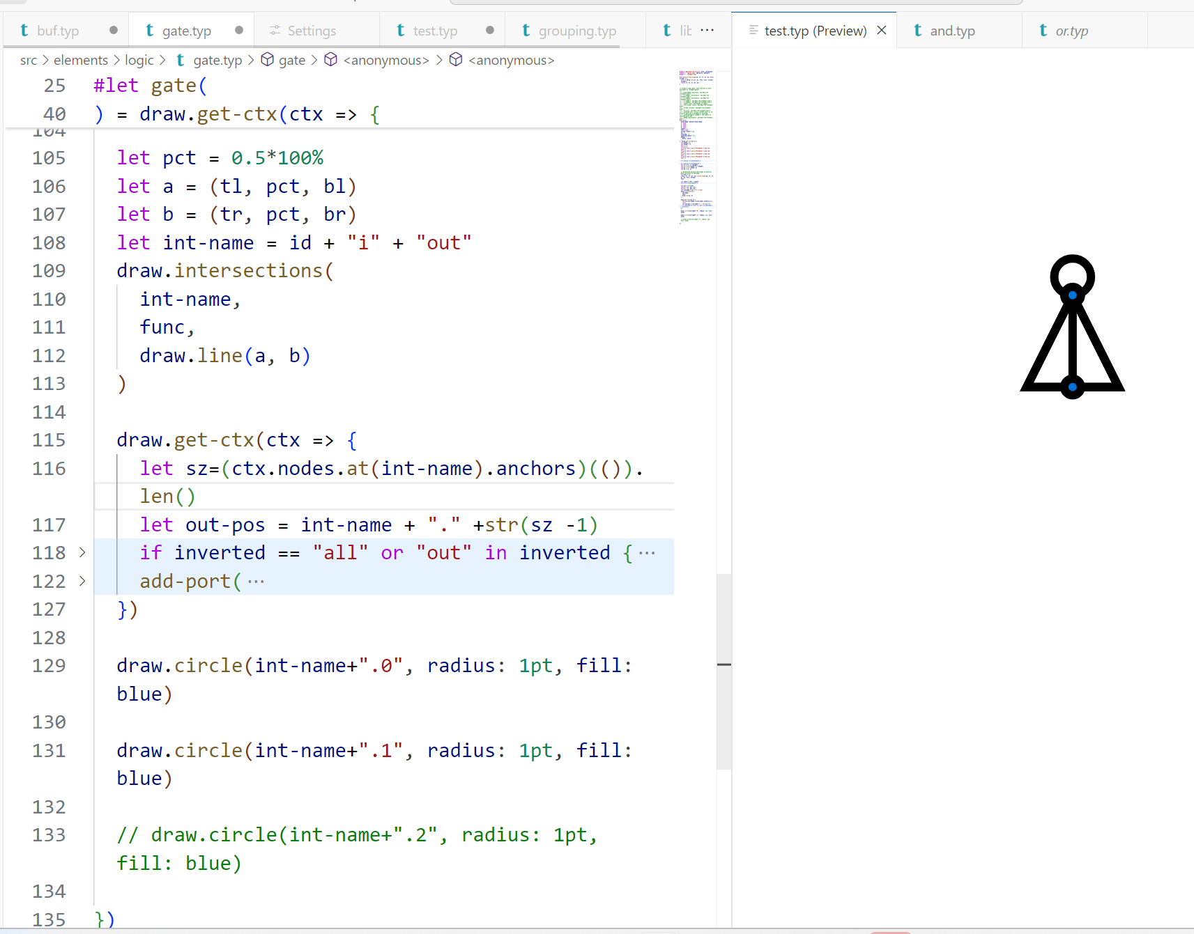
I found the input port of the rotated gate could render properly, so I changed the logic of output port by emulating the logic of input port, as shown below (the blue circles are intersections that I use to anchor the output), it works fine with NOT gate and AND gate

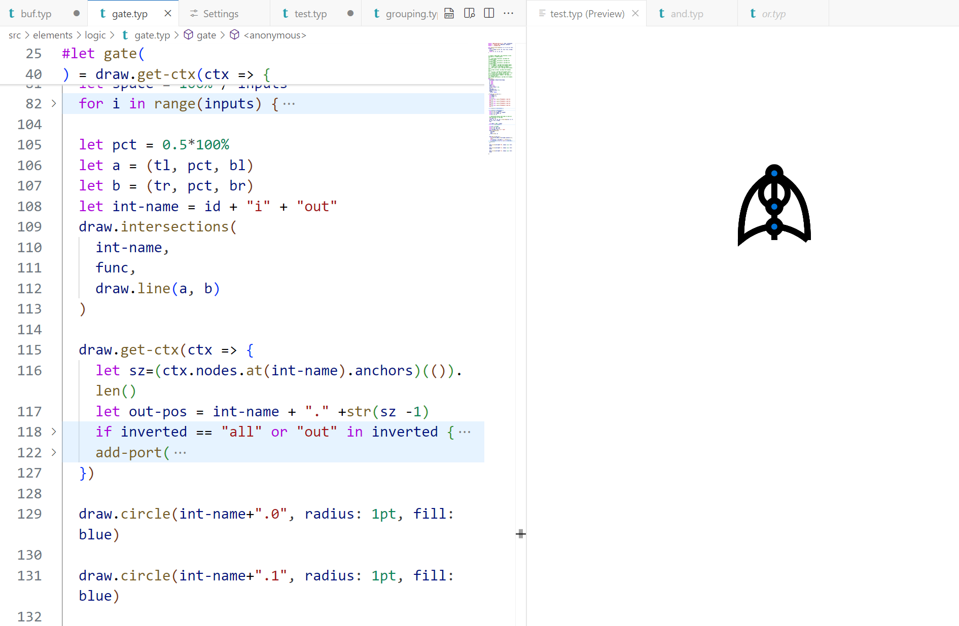
But it failed with XOR gate and OR gate, the circle of the inverted output port is inside of those two gates, which is not right. When I dive into the problem, I found a hidden line which is used to locate the "north" and "south" anchors, the hidden line only appears in the

draw-shapefunction of OR and XOR, so it disturbs the size of intersections, as shown belowIt seems that the logic of "draw" and "determine the anchors" is not well delineated:
draw_shapefunction is not only used for "draw", but also used for determine the "north" and "south" anchor, while thegatefunction is used for determine the "east", "west", "output" and other input anchorsdraw_shapefunction is specific to each gate, while thegatefunction is called by every gateSo I recommended to determine the "east", "west" and "output" anchors within the
draw_shapefunction, while leave the implementation of input anchors within thegatefunction.oh yeah it is not good to have draw and rotation mixed but I wouldn't know hot not to mix it with this architecture, I handle rotations here if you are interested
https://typst.app/project/pCiRocNZmVsfnFaeKR9rLn
I think the best way to add rotation is here
Yes, the pipeline here is not ideal, everything is mixed together
I'd like to make it more modular and better use CeTZ' features so that it'd be easier to add new components