adding nmos and pmos #6
Reference in New Issue
Block a user
Delete Branch "%!s()"
Deleting a branch is permanent. Although the deleted branch may continue to exist for a short time before it actually gets removed, it CANNOT be undone in most cases. Continue?
an attempt to add nmos and pmos
https://typst.app/project/rh20mdDbyd3OPJt98POytf
I added more circuit stuff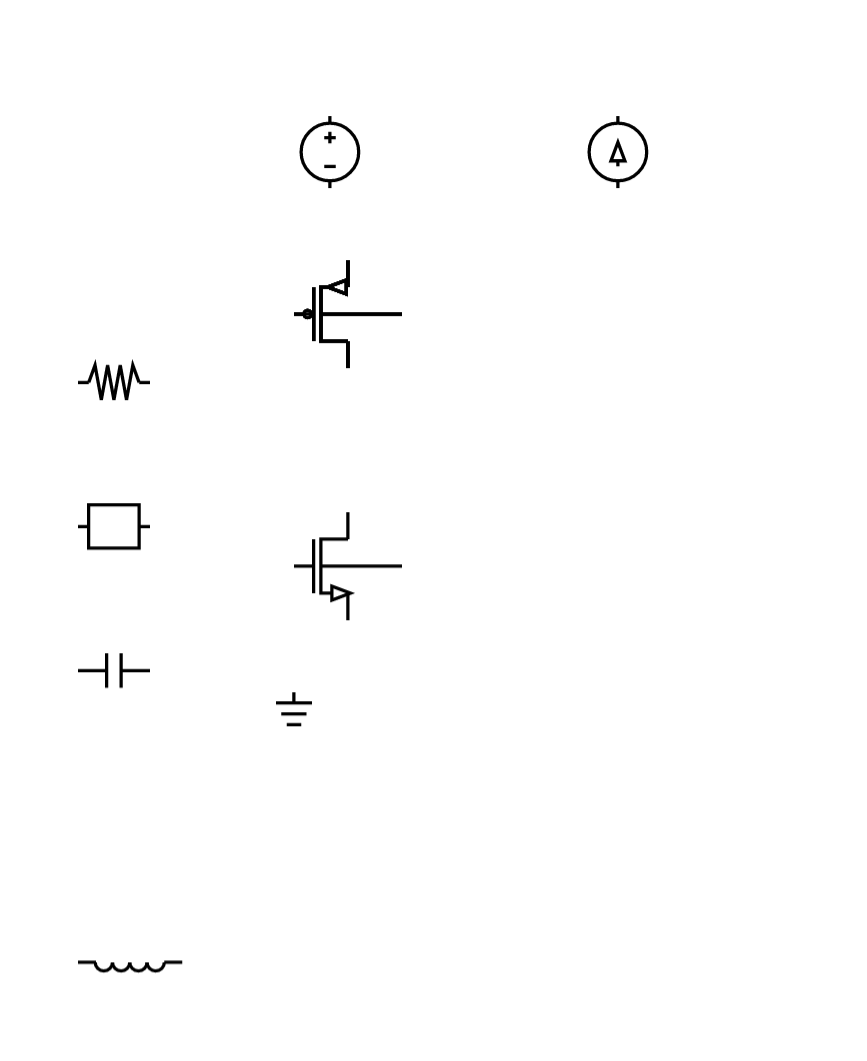
I'd like help by adding rotations
Thank you very much for your interest ! It looks very cool !
I had started working on some basic elements for resistors and capacitors but I haven't taken the time to finish it
Could you make this into a pull request ? I'll try to take a closer look ASAP
I would do a PR but I need assistance, where did you put the resistors and capacitors, quick question as well, how are you supposed to caption your elements?
You can take a look at the comp/electrical branch where I've added resistors and capacitors
What do you mean by caption ? Do you mean like the name displayed in blocks or extenders ? If so, that would be here :